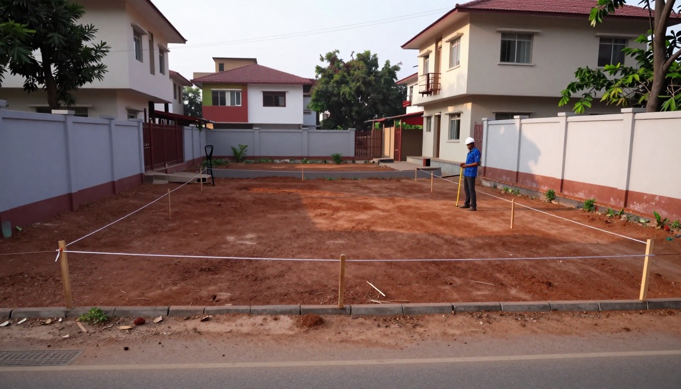


Whether you're planning to build a new home, renovate an existing property, or simply understand what your architect is proposing, reading house plans and architectural drawings is an essential skill. In India, where construction practices vary significantly across regions and building codes differ from state to state, having a clear understanding of architectural drawings becomes even more critical. This comprehensive guide will help you decode the symbols, lines, and notations used in architectural drawings, enabling you to make informed decisions about your construction project.
Understanding the Basics of Architectural Drawings
Architectural drawings are the visual language of construction. They communicate the design intent, spatial relationships, materials, and construction details in a standardized format that builders, contractors, and engineers can understand and execute. In India, these drawings must comply with the National Building Code (NBC) and local municipal regulations, which vary across states like Maharashtra, Karnataka, Tamil Nadu, and others.
The primary purpose of architectural drawings is to provide a complete and accurate representation of a building project before construction begins. This helps in obtaining necessary approvals from municipal authorities, estimating costs accurately, and ensuring that all stakeholders have a clear understanding of the project scope.
Build cost · Bengaluru, May 2026
Why Reading Plans Matters
Understanding architectural drawings protects your interests as a homeowner or project stakeholder. You can verify that the proposed design meets your requirements, identify potential issues before construction begins, and ensure that the final building matches your expectations. Additionally, clear comprehension of these drawings helps you communicate effectively with architects, engineers, and contractors—professionals you might find through platforms like AECORD that connect you with qualified AECO experts.
Types of Architectural Drawings Explained
Floor Plans
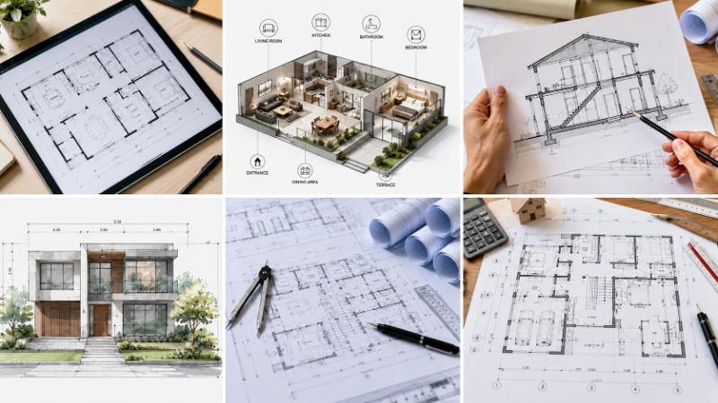
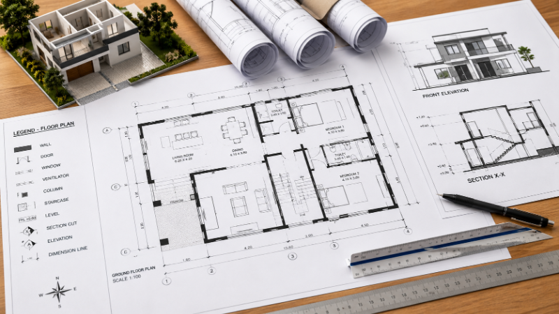
Floor plans are bird's-eye views of each level of a building, showing the layout of rooms, walls, doors, windows, and other features. They are typically drawn to a scale (commonly 1:100 or 1:50 in India) and represent what you would see if you looked down at the building from above with the roof removed.
In a floor plan, you'll notice:
Wall lines: Thick black or dark lines representing the building's structure
Door swings: Curved quarter-circle lines showing the direction doors open
Window symbols: Breaks in walls with specific notations
Dimensions: Measurements in millimeters, indicating room sizes and wall thicknesses
Room labels: Text identifying spaces like "Master Bedroom," "Living Room," or "Kitchen"
When reviewing floor plans for an Indian home, pay attention to compliance with local building bylaws. For instance, in Mumbai, the minimum carpet area for residential units and setback requirements are strictly regulated. Understanding these constraints in your floor plan helps ensure your design will receive municipal approval.
Frequently asked
Elevation Drawings
Elevations show the exterior (or interior) appearance of the building from different sides—front, rear, left, and right. These drawings display the height of the building, placement of windows and doors, roof lines, and external finishes like cladding or paint colors.
Elevations are crucial for understanding:
The building's visual appearance and architectural style
Window and door placements and sizes
Roof slopes and overhangs
External materials and finishes
Compliance with height restrictions and setback requirements
In Indian cities like Bangalore or Delhi, elevation drawings must demonstrate compliance with height restrictions and Vastu considerations, which some clients prefer. These drawings help you visualize how your home will look on the street and whether it harmonizes with the neighborhood character.
Section Drawings
Sections are vertical slices through the building, showing the internal height relationships, floor levels, roof structure, and how different spaces relate to each other vertically. They're drawn along a specific line shown on the floor plan (indicated by a cutting plane line with arrows).
Sections reveal:
Floor-to-floor heights and ceiling heights
Staircase design and riser heights
Roof structure and insulation details
Basement depths and foundation details
Vertical spatial relationships between rooms
For Indian homes, sections are particularly important for understanding compliance with minimum room heights (typically 2.7 to 3 meters for living spaces according to NBC guidelines) and verifying adequate ventilation and natural light provisions.
Detail Drawings
Detail drawings provide enlarged views of specific construction elements, showing how different materials and systems connect. These might include wall sections, staircase details, window frames, door assemblies, or kitchen layouts. Details are typically drawn at larger scales (1:10 or 1:5) to show construction clarity.
Details are essential for:
Understanding how materials meet and connect
Identifying waterproofing and damp-proofing measures
Specifying material qualities and finishes
Ensuring structural integrity
Facilitating accurate cost estimation
Decoding Architectural Symbols and Notations
Common Symbols in Indian Architectural Drawings
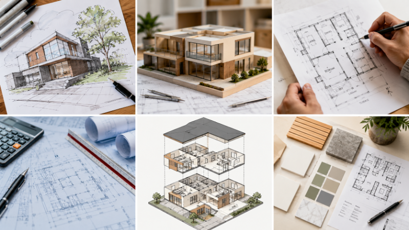
Architectural drawings use standardized symbols that represent various building elements. Understanding these symbols is crucial for accurate interpretation:
Walls: Thick solid lines (typically 200-300mm for load-bearing walls in India)
Doors: Represented by a break in the wall line with a swing arc showing the opening direction
Windows: Shown as breaks in walls with cross-hatching or specific patterns
Stairs: Depicted with parallel lines showing steps, with an arrow indicating the direction of ascent
Dimensions: Shown with dimension lines and arrows, typically in millimeters
Levels and heights: Indicated with elevation marks (like +0.00, +2.70, +5.40)
Electrical outlets and switches: Small circles or rectangles with specific notations
Plumbing fixtures: Standardized symbols for toilets, sinks, bathtubs, and water tanks
Different architectural firms in India may use slightly different conventions, so always refer to the legend or key provided with the drawing set. This legend explains all symbols used in that particular project's drawings./blog/how-to-read-architectural-drawings
Understanding Scales
Architectural drawings are always drawn to scale, meaning the drawing represents the actual building at a reduced size. Common scales used in India include:
1:100 - Most common for floor plans and elevations of residential buildings
1:50 - Used for detailed floor plans or smaller buildings
1:200 - Used for site plans and larger buildings
1:20 or 1:10 - Used for detail drawings
Always verify the scale mentioned on each drawing. When measuring on a drawing, use an architect's scale ruler (available in India for ₹200-500) rather than a regular ruler to maintain accuracy.
Reading Dimensions and Measurements
Dimensions on architectural drawings are typically shown in millimeters in India, though some older drawings might use meters. Always check the dimension notes on the drawing.
Types of Dimensions
Linear dimensions: Show lengths of walls, rooms, or building elements
Angular dimensions: Show angles, typically for sloped roofs or non-orthogonal walls
Radial dimensions: Show curved elements and their radius
Cumulative dimensions: Show total distances from a reference point
When reviewing a floor plan, verify that room dimensions make sense. For example, a "Master Bedroom" in an Indian home is typically at least 3.5m × 4m (approximately 140 square feet minimum), while a "Living Room" should ideally be at least 4m × 5m or larger depending on family size and lifestyle.
Interpreting Site Plans and Context
Site plans show the building's location on the property, including the building footprint, setbacks from property lines, parking areas, landscaping, and access points. They're essential for understanding how your building relates to the surrounding area.
Key Elements in Site Plans
Property boundaries: Shown with thick lines and dimensions
Building footprint: Outline of the building showing its position on the plot
Setbacks: Distances from property lines (critical for Indian municipal compliance)
Access roads: Showing vehicle and pedestrian circulation
Parking areas: Location and number of parking spaces
Utilities: Water, sewage, and electrical connections
North arrow: Indicating orientation (important for passive solar design in India)
In India, setback requirements vary significantly by location. In Delhi, for instance, front setbacks might be 3-6 meters depending on the road width, while in Bangalore, requirements differ. Always verify that your architect has incorporated the correct setbacks for your specific location and property size.
Material Specifications and Notations
Architectural drawings include notations indicating materials to be used in construction. These might appear as symbols within the drawing (like diagonal lines for concrete) or as written specifications in a legend.
Common Material Symbols
Concrete: Often shown with dots or stippled pattern
Brick: Shown with a brick-like pattern or small rectangles
Stone: Represented by irregular shapes
Wood: Shown with wood grain lines
Glass: Typically shown as clear areas with specific notation
For Indian construction, understanding material specifications is crucial for cost estimation. The difference between a cement concrete block (CCB) wall at ₹400-500 per square meter and a brick wall at ₹600-800 per square meter significantly impacts your project budget. Always cross-reference material symbols with the specifications document.
Understanding Structural and MEP Drawings
While architectural drawings focus on spatial design, structural drawings show how the building stands up, and MEP (Mechanical, Electrical, Plumbing) drawings show building systems.
Structural Drawings
These show the building's structural frame, including column locations, beam sizes, and load paths. While homeowners don't need to understand every structural detail, recognizing column locations helps you understand why walls are positioned certain ways and whether open floor plans are feasible.
MEP Drawings
Electrical drawings show outlet locations, switch placements, and lighting layouts. Plumbing drawings indicate water supply lines, drainage pipes, and fixture locations. HVAC drawings (in air-conditioned buildings) show ductwork and equipment placement. Understanding these helps you plan furniture placement and verify adequate outlets and switches for your lifestyle.
Common Mistakes When Reading Plans
Avoid these frequent errors when interpreting architectural drawings:
Ignoring the scale: Always check the scale before taking measurements from a drawing
Overlooking dimensions: Don't assume—always verify actual measurements rather than visual estimation
Missing the legend: Always refer to the drawing legend for symbol meanings
Not checking all sheets: A complete drawing set includes multiple sheets; review all relevant sheets
Forgetting about vertical relationships: Always cross-reference floor plans with sections to understand full spatial relationships
Neglecting compliance details: Verify that setbacks, heights, and other regulatory requirements are met
Tips for Effective Plan Review
When reviewing architectural drawings for your project, follow this systematic approach:
Start with the site plan: Understand the overall context and building orientation
Review floor plans systematically: Check each room, verify dimensions, and trace circulation paths
Study elevations: Visualize how the building will look and verify aesthetic preferences
Cross-reference with sections: Understand vertical relationships and verify ceiling heights
Review details: Examine material specifications and construction methods
Check for consistency: Ensure all drawings are coordinated and dimensions match across sheets
Verify compliance: Confirm that the design meets local building codes and regulations
Ask questions: Don't hesitate to ask your architect to clarify anything unclear
Using Technology to Review Plans
Modern tools make plan review easier. Many architects now provide digital versions of drawings in PDF or specialized software formats. Some useful approaches include:
PDF viewers: Use zoom and measurement tools in PDF software
CAD software: Free tools like LibreCAD or online viewers let you examine CAD files
3D visualization: Some architects provide 3D models or renderings to help visualize the final design
Markup tools: Use annotation features to mark up drawings with questions or notes

When to Seek Professional Help
While understanding the basics of architectural drawings is valuable, certain situations warrant professional consultation. If you're uncertain about structural implications, regulatory compliance, or complex MEP systems, consult with qualified professionals. Finding experienced architects and engineers in your area is made easier through platforms like AECORD, which connects you with verified AECO professionals who can review drawings and provide expert guidance.
A structural engineer can verify that open floor plans are feasible, a compliance consultant can ensure municipal approval likelihood, and an MEP engineer can optimize building systems. These investments often save money by preventing costly mistakes during construction.
Conclusion
Reading house plans and architectural drawings is a learnable skill that empowers you to make informed decisions about your construction project. By understanding the different types of drawings, recognizing common symbols, and following a systematic review process, you can effectively communicate with your design team and ensure your vision becomes reality.
In the Indian context, where building regulations vary by location and construction practices differ across regions, having a clear grasp of architectural drawings becomes even more important. Whether you're building in Delhi, Mumbai, Bangalore, or any other Indian city, these principles remain consistent.
As you embark on your construction journey, don't hesitate to seek professional guidance when needed. If you're looking for qualified architects, structural engineers, or construction professionals to help with your project, explore AECORD's marketplace to connect with verified AECO experts in your area. With proper understanding of your architectural drawings and the right professional team supporting you, you're well-positioned for a successful construction project that meets your expectations and complies with all regulatory requirements.
Frequently Asked Questions
What is the purpose of architectural drawings in construction?
Architectural drawings serve as the visual language of construction, communicating design intent, spatial relationships, materials, and construction details in a standardized format. They help obtain municipal approvals, estimate costs accurately, and ensure all stakeholders understand the project scope before construction begins.
What do the symbols and lines in floor plans mean?
Floor plans use specific symbols to represent building elements: thick black lines for walls, curved quarter-circle lines for door swings, breaks in walls for windows, and measurements in millimeters for dimensions. Room labels identify spaces like bedrooms and kitchens, providing a bird's-eye view of each building level.
Why is it important to understand architectural drawings as a homeowner?
Understanding architectural drawings protects your interests by allowing you to verify the design meets your requirements, identify potential issues before construction, and ensure the final building matches your expectations. It also enables effective communication with architects, engineers, and contractors throughout the project.
What information do elevation drawings show?
Elevation drawings display the exterior or interior appearance of a building from different sides (front, rear, left, right), showing building height, window and door placements, roof lines, external finishes, and compliance with local height and setback requirements.
What building codes must architectural drawings comply with in India?
Architectural drawings in India must comply with the National Building Code (NBC) and local municipal regulations, which vary across states like Maharashtra, Karnataka, and Tamil Nadu. These regulations cover aspects like minimum carpet areas, setback requirements, and height restrictions specific to each region.