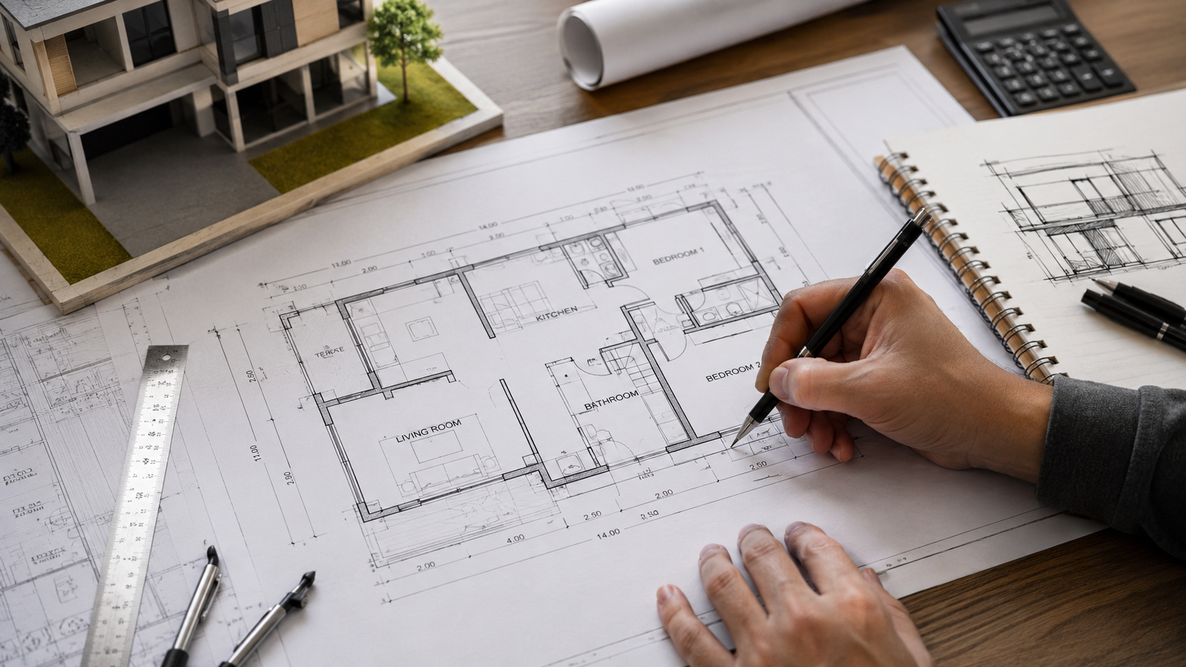


In architecture and construction, understanding the differences between floor plans, elevations, and sections is fundamental to effective design communication and project execution. Whether you're a homeowner planning a renovation, a contractor managing construction, or an architect designing a new structure, these three drawing types form the backbone of architectural documentation in India and globally.
These technical drawings serve as the visual language between designers, engineers, contractors, and clients. Without clear understanding of what each drawing represents, misinterpretations can lead to costly errors, delays, and disputes on construction sites. This comprehensive guide will help you understand each drawing type, their purposes, and how they work together in the Indian construction context./blog/how-to-read-house-plans-and-architectural-drawings-a-beginner-s-guide
Understanding Architectural Drawings: The Foundation
Architectural drawings are standardized visual representations of a building or structure. They communicate design intent, dimensions, materials, and construction details in a language that professionals across the AECO industry can understand uniformly. In India, these drawings must comply with Bureau of Indian Standards (BIS) guidelines and local municipal building bylaws.
The three primary drawing types—floor plans, elevations, and sections—provide different perspectives of the same structure. Together, they create a complete three-dimensional understanding of a project. When you're searching for qualified architects or engineers on AECORD, you'll find professionals experienced in creating these essential documents for residential, commercial, and industrial projects across Indian cities.
Build cost · Bengaluru, May 2026
Floor Plans: The Bird's Eye View
What is a Floor Plan?
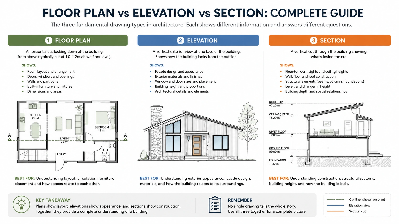
A floor plan is a horizontal cross-section view of a building, typically drawn at a scale of 1:100 or 1:50. Imagine slicing through your building about 1.5 meters above the floor and looking down from above—that's essentially what a floor plan shows. It displays the layout of rooms, walls, doors, windows, and spatial relationships on a single level.
Key Elements in a Floor Plan
Wall layouts: Shows the position and thickness of walls, which is crucial for understanding load-bearing capacity and structural integrity
Door and window placements: Indicates swing direction of doors and window locations, essential for functionality and ventilation planning
Dimensions: Provides measurements for rooms, hallways, and overall floor dimensions in meters
Room labels: Identifies each space (bedroom, kitchen, bathroom, living room, etc.)
Fixtures: Shows placement of bathrooms, kitchens, staircases, and permanent installations
Circulation paths: Illustrates how people move through the space
Area calculations: Total built-up area, carpet area, and super built-up area as per Indian standards
Frequently asked
Practical Uses of Floor Plans in India
In the Indian context, floor plans are essential for:
Municipal approvals: Required for obtaining building permits from local municipal corporations in cities like Mumbai, Delhi, Bangalore, and Pune
Space planning: Helps homeowners and business owners optimize their space utilization
Furniture arrangement: Enables clients to visualize furniture placement before construction or renovation
Regulatory compliance: Ensures adherence to setback requirements, floor space index (FSI), and parking norms specified by local authorities
Cost estimation: Allows contractors to calculate material requirements and labor costs accurately
For example, a 2 BHK apartment in Bangalore with a carpet area of 900 sq.ft. (approximately 84 sq.m.) would show the exact placement of bedrooms, bathrooms, kitchen, and living areas in the floor plan, helping buyers understand the spatial layout before purchase.
Floor Plan Variations
Different types of floor plans serve specific purposes:
Architectural floor plans: Detailed plans showing all structural elements
Furniture plans: Shows proposed furniture layout and interior design
Electrical plans: Indicates switch locations, outlets, and electrical distribution
Plumbing plans: Shows water supply lines, drainage, and sanitary fixtures
HVAC plans: Displays air conditioning and ventilation system layout
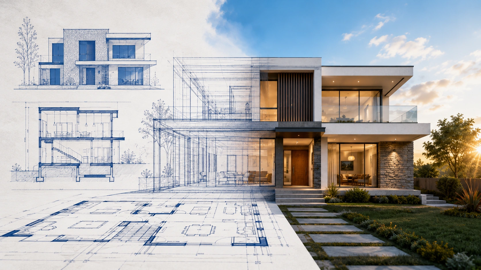
Elevations: The Front-Facing View
What is an Elevation?
An elevation is a vertical projection of a building's exterior or interior wall. It shows what the building looks like when viewed from a specific direction—front, rear, left side, or right side. Elevations are drawn at the same scale as floor plans (typically 1:100 or 1:50) and provide crucial information about the building's appearance, height, and vertical relationships.
Types of Elevations
Exterior elevations: Show the building's facade, including architectural features, materials, colors, and finishes visible from outside
Interior elevations: Display wall treatments, built-in features, and details visible from inside specific rooms
Front elevation: The primary facade facing the street or main approach
Rear and side elevations: Show the building from other perspectives
Information Contained in Elevations
Building height: Total height from ground level, important for compliance with municipal height restrictions
Window and door heights: Vertical positioning of openings relative to floor levels
Material finishes: Brick, stone, paint colors, cladding, and other exterior materials
Architectural details: Cornices, parapets, balconies, and decorative elements
Vertical dimensions: Floor-to-floor heights, parapet heights, and setback lines
Structural elements: Columns, beams, and other visible structural components
Landscaping: Trees, shrubs, and ground-level features
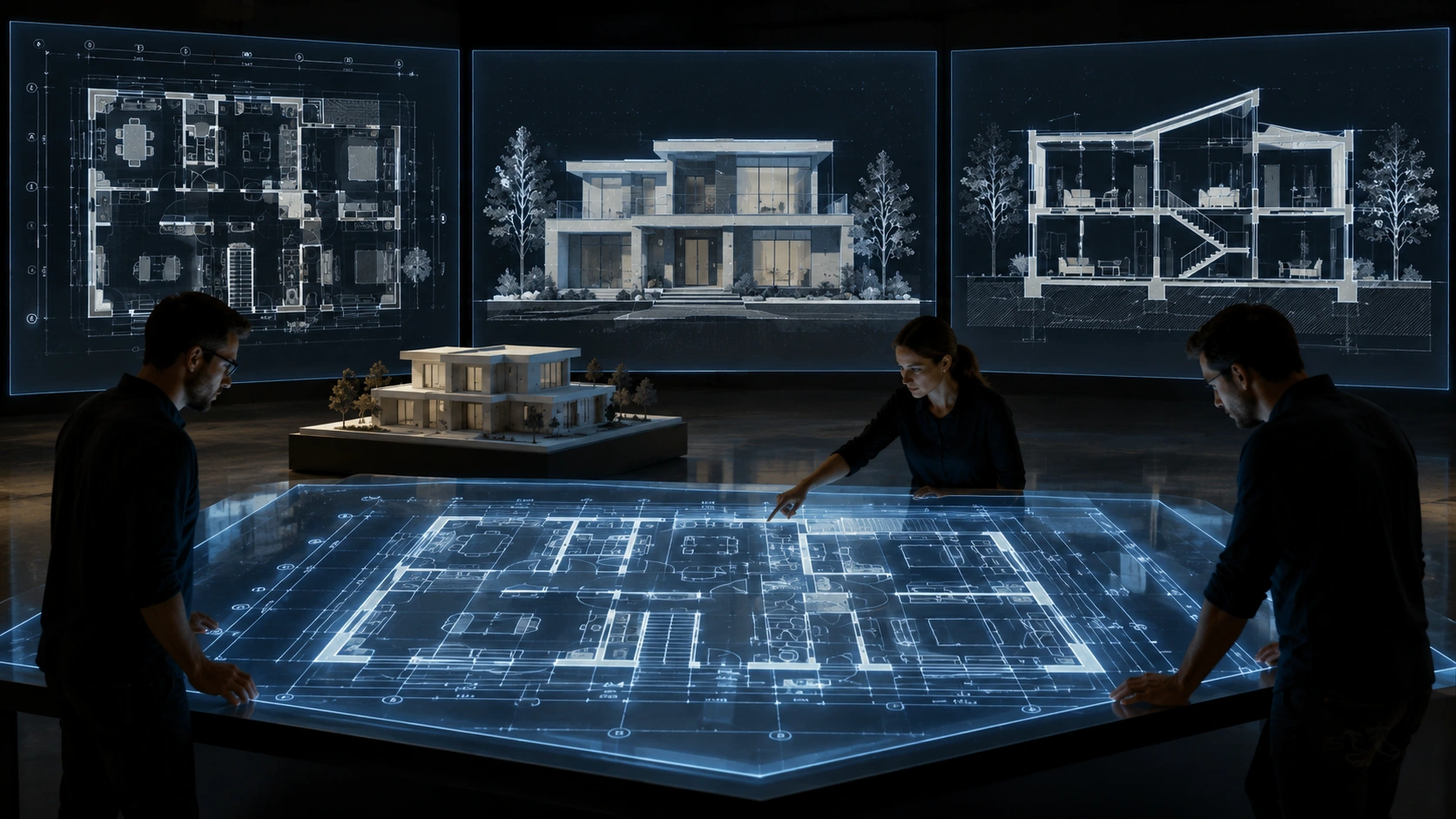
Elevations in Indian Construction Practice
In India, elevations serve critical regulatory functions. Municipal authorities in cities like Mumbai, Delhi, Hyderabad, and Chennai require front elevations to verify:
Compliance with setback requirements (distance from property boundaries)
Adherence to maximum building height restrictions
Architectural compatibility with neighborhood standards
Proper placement of utilities and external features
For residential projects, elevations help buyers visualize the final aesthetic appeal. For commercial buildings, elevations communicate brand identity and professional image. When working with professionals on AECORD, you can find architects who specialize in creating elevations that balance aesthetic appeal with regulatory compliance across various Indian cities./blog/how-to-read-architectural-drawings
Common Elevation Challenges
Creating effective elevations in the Indian context involves navigating:
Climate considerations: Designing overhangs and shading devices for intense sun exposure in cities like Delhi and Jaipur
Material availability: Selecting finishes that are locally available and cost-effective in INR
Monsoon protection: Ensuring proper drainage and water-resistant details for cities with heavy rainfall like Mumbai and Bangalore
Aesthetic preferences: Balancing traditional architectural styles with modern design trends
Sections: The Sliced View
What is a Section?
A section is a vertical slice through a building, showing the interior height relationships, floor levels, and structural depth. If you imagine cutting a vertical plane through your building and looking at the exposed face, that's a section. Sections reveal information that floor plans and elevations cannot—the vertical story of how spaces relate to each other in height and depth.
Types of Sections
Longitudinal sections: Cut lengthwise through the building, typically showing the longest dimension
Transverse sections: Cut across the width of the building
Detail sections: Magnified views of specific areas showing construction details
Wall sections: Show how walls are constructed, including layers of materials
Critical Information in Sections
Floor-to-floor heights: Vertical distance between consecutive floor levels (typically 3.0-3.5 meters in residential buildings in India)
Ceiling heights: Clear height available for occupants
Staircase design: Rise, run, and overall dimensions of stairs
Roof structure: Pitch, type, and height of roof elements
Material layers: Shows construction composition of walls, floors, and roofs
Structural elements: Beams, columns, and their positioning
Vertical circulation: Elevators, escalators, and their spatial requirements
Clearances: Headroom, setbacks, and other spatial requirements
Sections in Indian Building Context
Sections are particularly important in India for:
Multi-story buildings: Clearly showing how residential floors stack and relate to each other
Sloped sites: Demonstrating how buildings adapt to hilly terrain in cities like Shimla, Ooty, and Pune
Basement design: Showing depth of basements relative to ground level and water table
Structural verification: Ensuring adequate clearances for beams and columns
Accessibility compliance: Verifying ramp slopes and elevator requirements per Indian Standards
For a residential building in Bangalore, sections would show how each floor is positioned relative to the sloped site, where basements begin, and how the roof structure accommodates the local climate. These details are essential for structural engineers and contractors executing the project accurately.
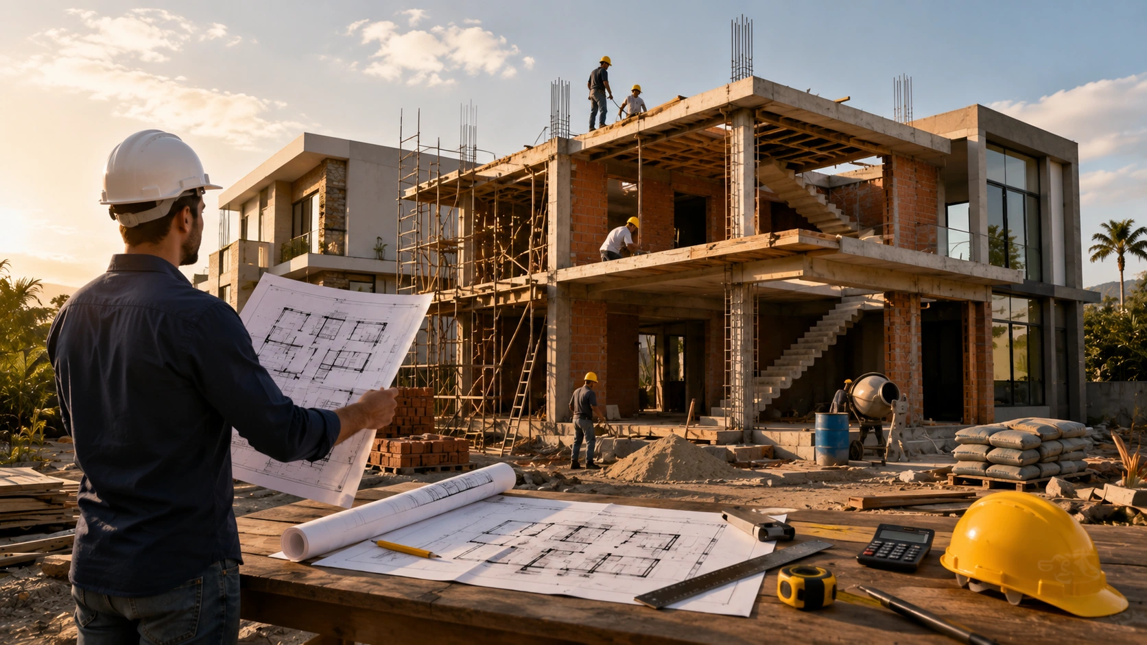
How Floor Plans, Elevations, and Sections Work Together
The Integrated Drawing System
These three drawing types are interconnected and complementary. A dimension shown in a floor plan must match the corresponding dimension in an elevation. A floor level indicated in a section must align with the floor plan. This consistency is crucial for construction accuracy.
Consider a simple example: A window shown in a floor plan must appear in the corresponding elevation at the correct height and width. The section must show the window opening at the same height relative to the floor level. Any inconsistency between these drawings creates confusion and potential construction errors.
Cross-Referencing and Coordination
Professional architectural documents include:
Reference markers: Lines on floor plans indicating where sections are cut
Dimension consistency: Same measurements appearing on multiple drawing types
Matching scales: All drawings at consistent scales (typically 1:100 for general plans)
Coordinated notes: Details referenced across multiple drawings
Reading Complete Drawing Sets
A complete architectural drawing set for an Indian residential or commercial project typically includes:
Site plans showing property boundaries and building position
Multiple floor plans (one for each level)
All four elevations (front, rear, left, right)
Multiple sections (at least one longitudinal and one transverse)
Detail drawings showing specific construction methods
Electrical, plumbing, and HVAC plans
Structural drawings showing column and beam layouts
Common Mistakes and Misinterpretations
Typical Errors in Reading Drawings
Ignoring scale: Assuming all drawings are 1:1 instead of checking the stated scale
Misunderstanding wall thickness: Not recognizing that wall lines in floor plans have thickness
Confusing door swing: Misinterpreting which direction a door opens based on the arc symbol
Overlooking hidden lines: Missing elements shown with dashed lines (hidden or future elements)
Dimension inconsistencies: Not verifying that dimensions match across different drawing types
Design Issues Revealed by Complete Drawing Sets
When reviewing floor plans, elevations, and sections together, several design problems become apparent:
Structural columns blocking doorways or windows
Ceiling heights too low for planned uses
Windows positioned where they can't be opened due to external elements
Stairs with inconsistent rises that violate building codes
Inadequate headroom in basements or under beams
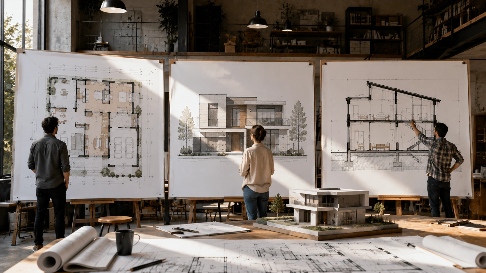
Digital Tools and Modern Practices
CAD and BIM in India
Today's architectural practice in India increasingly uses:
CAD software: AutoCAD and similar tools for creating precise 2D drawings
BIM (Building Information Modeling): 3D models that automatically generate floor plans, elevations, and sections with coordinated information
3D visualization: Renderings and walkthroughs helping clients understand designs before construction begins
Cloud collaboration: Allowing multiple team members to work on drawings simultaneously
When you engage professionals through AECORD, many architects and engineers use these modern tools to create coordinated, accurate drawing sets that minimize errors and improve project execution.
Advantages of Digital Documentation
Automatic consistency checking between drawings
Easy modification and version control
Quick generation of cost estimates
Better visualization for clients and stakeholders
Compliance verification against building codes
Practical Tips for Homeowners and Developers
When Reviewing Your Project Drawings
Check dimensions: Verify that room sizes match your expectations and that total area matches the quoted carpet area
Verify window placement: Ensure windows provide adequate natural light and ventilation for each room
Review door swings: Confirm that doors don't block furniture placement or create traffic flow issues
Examine ceiling heights: In India, residential buildings typically have 2.7-3.0 meter floor-to-ceiling heights; commercial spaces may be higher
Check parking and setbacks: Verify compliance with municipal requirements for parking spaces and setback distances
Review utility locations: Ensure electrical panels, water meters, and other utilities are conveniently positioned
Questions to Ask Your Architect
Are these drawings compliant with local municipal bylaws and BIS standards?
What is the total built-up area, carpet area, and super built-up area?
How do the floor-to-floor heights compare to similar buildings in the area?
Are sections drawn to show critical relationships like staircase dimensions and basement depth?
What is the cost estimate based on these drawings?
Have elevations been designed to suit the local climate and neighborhood character?
Cost Implications in Indian Construction
Understanding floor plans, elevations, and sections has direct cost implications:
Carpet area vs. built-up area: In Indian real estate, you typically pay per square foot of carpet area (usable space), not built-up area (including walls and common areas). A 1000 sq.ft. carpet area apartment might have 1200-1300 sq.ft. built-up area
Material selection from elevations: Facade materials shown in elevations significantly impact project costs. Stone cladding costs ₹150-300 per sq.ft., while painted brick costs ₹30-50 per sq.ft.
Structural complexity from sections: Sloped sites requiring complex sections might increase structural costs by 15-25%
Basement depth: Deeper basements (shown in sections) increase excavation and waterproofing costs significantly
Regulatory Compliance in Indian Cities
Different Indian cities have specific requirements for these drawings:
Mumbai: FSI regulations, coastal regulations, and specific setback requirements
Delhi: Master Plan compliance, heritage considerations in certain areas
Bangalore: Bangalore Development Authority (BDA) regulations, water harvesting requirements
Pune: Pune Municipal Corporation bylaws, green building requirements
Hyderabad: GHMC regulations, lake protection zones
Professional architects using AECORD are familiar with these city-specific requirements and create drawings that navigate local regulations effectively.
Conclusion: The Complete Picture
Floor plans, elevations, and sections are the fundamental language of architectural communication. Floor plans show spatial relationships horizontally, elevations display the building's appearance and vertical dimensions, and sections reveal the internal height relationships and structural organization. Together, they provide a complete three-dimensional understanding of a building.
Whether you're planning a residential renovation in Mumbai, developing a commercial property in Bangalore, or constructing an industrial facility in Pune, understanding these drawing types ensures better communication with your design and construction team. They form the basis for accurate cost estimation, regulatory compliance, and successful project execution.
As you plan your next construction or renovation project, take time to thoroughly review the floor plans, elevations, and sections with your architect or engineer. Ask questions about dimensions, materials, and compliance with local regulations. These drawings represent your investment and vision—they deserve careful attention.
Ready to find experienced architects and engineers who excel at creating clear, compliant, and beautiful architectural drawings for your project? Explore AECORD, India's leading B2B2C marketplace for AECO professionals. Connect with qualified architects, structural engineers, and construction professionals across major Indian cities who understand local regulations, climate considerations, and best practices. Post your project requirements today and receive proposals from vetted professionals ready to bring your vision to life with precise, coordinated architectural drawings.
Frequently Asked Questions
What is the difference between a floor plan, elevation, and section in architecture?
A floor plan is a horizontal bird's-eye view showing room layouts and spatial relationships, an elevation is a vertical front or side view showing the building's exterior appearance, and a section is a vertical slice through the building showing interior heights and relationships. Together, these three drawing types provide a complete three-dimensional understanding of a structure.
Why are floor plans important for construction projects in India?
Floor plans are essential for obtaining municipal building permits, ensuring regulatory compliance with local bylaws, calculating accurate cost estimates, and optimizing space utilization. They must comply with Bureau of Indian Standards (BIS) guidelines and specify setback requirements, floor space index (FSI), and parking norms.
What information does a floor plan show?
A floor plan displays wall layouts, door and window placements with swing directions, room dimensions, space labels, fixture locations (bathrooms, kitchens, staircases), circulation paths, and area calculations including built-up area and carpet area as per Indian standards.
What scale are architectural floor plans typically drawn at?
Floor plans are typically drawn at a scale of 1:100 or 1:50, which means 1 unit on the drawing represents 100 or 50 units in actual size. This standardized scaling allows professionals to accurately interpret dimensions and spatial relationships.
How do floor plans help with furniture arrangement and space planning?
Floor plans enable clients to visualize furniture placement and room layouts before construction or renovation begins, helping optimize space utilization and identify potential circulation issues. This allows homeowners and business owners to make informed decisions about their spatial design.