Whether you're a homeowner reviewing your architect's designs, a construction professional managing a project, or an aspiring builder, understanding how to read house plans and architectural drawings is essential. These documents form the blueprint of any construction project, and misinterpreting them can lead to costly mistakes, delays, and structural issues.
In India, where construction standards vary across states and municipalities, having a clear understanding of architectural drawings becomes even more critical. This comprehensive guide will walk you through the fundamentals of reading house plans and architectural drawings, helping you make informed decisions about your project.

Understanding the Basics of Architectural Drawings
Architectural drawings are technical documents that communicate design intent, dimensions, materials, and construction methods. They're created to a specific scale and include standardized symbols and notations that professionals use across the industry.
Build cost · Bengaluru, May 2026
What Are the Different Types of Architectural Drawings?
Before diving into how to read them, it's important to understand the various types of drawings you'll encounter:
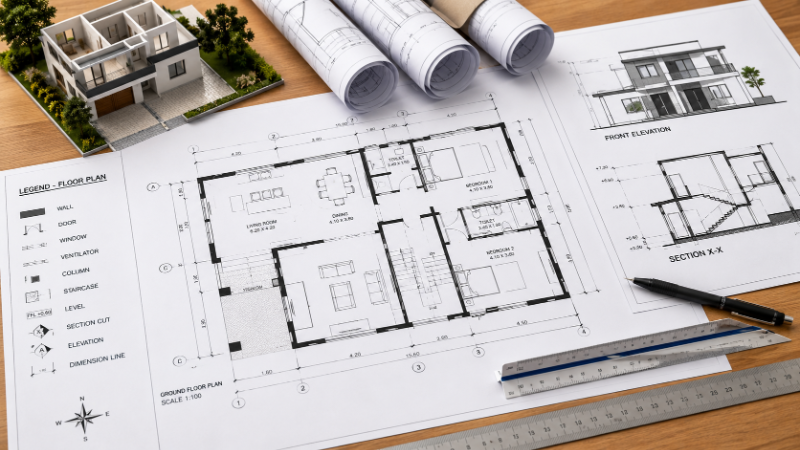
Floor Plans: These are bird's-eye views showing room layouts, dimensions, and wall placements. They're typically drawn at scales like 1:100 or 1:50.
Elevations: These show the exterior or interior vertical faces of a building, displaying height, materials, and architectural features.
Sections: These are vertical slices through the building, showing how different levels relate to each other and revealing interior heights.
Site Plans: These illustrate the property boundary, building placement, access roads, parking areas, and landscaping.
Details: These are enlarged drawings focusing on specific construction methods, connections, and material specifications.
Schedules: These list specifications for doors, windows, finishes, and other components.
Decoding Floor Plans
Floor plans are the most commonly referenced drawings and form the foundation for understanding any architectural project. Learning to read them properly is your first step toward becoming fluent in architectural language.
Understanding Scale and Dimensions
Every architectural drawing includes a scale, which indicates the relationship between the drawing size and the actual building size. Common scales in India include:
1:100 – Commonly used for overall floor plans (1 cm on drawing = 1 meter in reality)
1:50 – Used for more detailed floor plans
1:20 – Used for detailed sections and construction details
1:10 – Used for very detailed construction elements
Always check the scale box on your drawing before making assumptions. Never estimate measurements by eye—always refer to the dimensions marked on the plan. In Indian architectural standards, dimensions are typically shown in millimeters (mm) or meters (m).
Frequently asked
Reading Dimension Lines and Annotations
Dimensions on floor plans are shown with thin lines with arrows or ticks at both ends. These indicate the distance between walls, openings, or other features. When reading dimensions:
Read dimensions from left to right and bottom to top
Note that dimensions are measured face-to-face of walls or center-to-center, depending on the drawing convention
Pay attention to cumulative dimensions—adding up individual room dimensions should equal the total building dimension
Check for any dimension notations like "varies" or "as required," which indicate flexibility in that measurement
Interpreting Wall Symbols and Thicknesses
Walls are shown as parallel lines, with the thickness indicating the actual wall construction. In Indian residential construction, you'll typically see:
Exterior walls: Usually 200-300mm thick (including brick, insulation, and plaster)
Interior load-bearing walls: 200-250mm thick
Interior partition walls: 100-150mm thick
Different line weights (thicker or thinner lines) often indicate different wall types. Always refer to the legend or notes on the drawing to understand what each line weight represents.
Recognizing Door and Window Symbols
Doors and windows are represented by standardized symbols on floor plans. Doors are typically shown as a quarter-circle arc (called a swing line) indicating the door opening direction. Windows are shown as breaks in the wall line with cross-hatching or specific patterns.
Look for door and window schedules on your drawing set—these tables provide crucial information about:
Door and window types and sizes
Materials (aluminum, wood, uPVC)
Glass specifications
Hardware requirements
Glazing patterns
This is particularly important in Indian construction, where window and door specifications must comply with local building codes and climate considerations.
Understanding Elevation Drawings
While floor plans show horizontal relationships, elevation drawings reveal the vertical character of your building. These drawings show what the building looks like from the front, back, and sides.
Reading Height and Vertical Relationships
Elevations display the building's height, floor levels, roof forms, and exterior materials. Key elements to look for include:
Finished floor levels (FFL): These indicate the height of each floor relative to a reference point (usually ground level)
Roof height: Shows the peak or highest point of the building
Parapet height: The wall extending above the roof line
Door and window heights: Showing sill heights and lintel positions
In Indian cities like Mumbai, Bangalore, and Delhi, building heights are regulated by local municipal corporations. Your elevation drawing should indicate compliance with these height restrictions, which vary based on setback distances and floor area ratio (FAR) regulations.
Identifying Material Finishes on Elevations
Elevations use various patterns and symbols to indicate different materials:
Brick patterns for masonry walls
Horizontal lines for concrete surfaces
Dotted patterns for stone cladding
Specific symbols for metal, glass, or wood finishes
Always cross-reference the material legend and finish schedules to understand exactly what materials are specified for each elevation.
Deciphering Section Drawings
Section drawings are perhaps the most challenging for beginners but provide invaluable information about how the building is constructed vertically. A section is created by slicing vertically through the building and showing the profile.
Understanding Vertical Construction Details
Sections reveal:
Floor-to-floor heights
Staircase dimensions and runs
Ceiling heights and suspended ceiling details
Roof construction and slope
Foundation depth and type
How different building elements connect
In Indian construction, sections are critical for understanding how buildings manage monsoon drainage, thermal performance, and seismic considerations. For instance, a section might show how a sloped roof directs rainwater away from the structure or how ventilation is maintained in humid climates like Kerala or coastal areas.
Reading Section Markers on Floor Plans
Sections are referenced from floor plans using a line with arrows at both ends and a label (like "Section A-A"). This line indicates exactly where the vertical slice is taken through the building. Always locate this line on the floor plan before reading the corresponding section drawing.
Interpreting Symbols and Legends
Architectural drawings use a standardized set of symbols and abbreviations. Understanding these is crucial for accurate interpretation.
Common Architectural Symbols
Dimension lines: Thin lines with arrows showing measurements
Center lines: Alternating short and long dashes indicating symmetry or centerlines
Hidden lines: Dashed lines showing elements not visible from that view
Grid lines: Numbered and lettered lines used as reference coordinates
Level indicators: Symbols showing floor heights and elevations
North arrow: Shows building orientation (crucial for understanding sun exposure and ventilation)
Understanding Abbreviations
Indian architectural drawings commonly use abbreviations such as:
FFL: Finished Floor Level
DPC: Damp Proof Course
RCC: Reinforced Cement Concrete
FAR: Floor Area Ratio
RoW: Right of Way
GL: Ground Level
BUA: Built-Up Area
Always refer to the drawing's abbreviations list if you're unfamiliar with any notation.
Practical Tips for Reading House Plans
Establish a Systematic Approach
When reviewing a new set of drawings:
Start with the site plan to understand the building's location and orientation
Move to floor plans, reading each level from bottom to top
Review elevations to understand the building's external appearance
Study sections to understand vertical relationships
Examine details for specific construction methods
Cross-reference schedules for material specifications
Check for Consistency and Conflicts
Professional architects and engineers prepare coordinated drawing sets, but errors can occur. As you review:
Verify that dimensions on floor plans match section drawings
Ensure door and window locations align across all drawings
Check that room dimensions are consistent throughout the set
Look for any conflicting information between different drawing types
If you identify inconsistencies, document them and request clarification from your architect before construction begins.
Understand Indian Building Code Requirements
Indian architectural drawings must comply with the National Building Code (NBC) and local municipal regulations. Key aspects to verify include:
Setbacks: Distance from property boundaries
Floor Area Ratio (FAR): The ratio of built-up area to plot area
Open space requirements: Minimum courtyard and open area dimensions
Staircase dimensions: Tread and riser dimensions, handrail requirements
Accessibility requirements: Ramps, accessible bathrooms, and circulation spaces for persons with disabilities
Parking requirements: Minimum parking spaces based on building type and area
Visualize the Space in Three Dimensions
Floor plans are two-dimensional, but buildings are three-dimensional. As you study plans:
Imagine walking through each room
Visualize how natural light enters through windows
Consider traffic flow between spaces
Think about how furniture will fit in the spaces
Evaluate the relationship between different areas
This mental exercise helps identify potential design issues before construction begins.
Common Mistakes When Reading Architectural Drawings
Avoid these frequent errors:
Ignoring the scale: Always verify the drawing scale before making assumptions about size
Misinterpreting symbols: Different architects may use slightly different conventions—always check the legend
Assuming unmarked dimensions: Never estimate—if a dimension isn't marked, ask for clarification
Overlooking notes: Important information often appears in notes, schedules, and specifications, not just on the drawings themselves
Neglecting to check all sheets: Information may be distributed across multiple drawing sheets
Missing section references: Always locate section cut lines on floor plans to understand where vertical slices are taken

When to Seek Professional Help
While understanding how to read architectural drawings is valuable, complex projects benefit from professional guidance. If you're:
Building a multi-story residential or commercial project
Working on a renovation with structural modifications
Dealing with complex mechanical, electrical, or plumbing systems
Uncertain about regulatory compliance in your specific municipality
Consider consulting with qualified architects, structural engineers, or project managers who can review drawings and ensure compliance with local codes.
AECORD connects you with experienced architecture and engineering professionals across India who can guide you through drawing interpretation and project execution. Whether you need clarification on existing drawings or require new architectural designs for your project, finding the right professional on AECORD ensures your project is built correctly from the start.
Conclusion
Learning to read house plans and architectural drawings is a valuable skill that empowers you to participate meaningfully in your construction project. By understanding scales, dimensions, symbols, and the relationships between different drawing types, you can identify issues early, communicate effectively with professionals, and ensure your vision is accurately translated into built form.
Remember that architectural drawings are the language of construction. Misunderstandings in this language can lead to expensive corrections and project delays. Take time to thoroughly review all drawings, ask questions when something isn't clear, and don't hesitate to seek professional clarification.
Whether you're a homeowner planning your dream house in Pune, a developer managing a commercial project in Bangalore, or a contractor overseeing construction in Mumbai, these fundamental skills will serve you well. Ready to connect with architectural professionals who can help you navigate your next project? Explore AECORD's network of qualified architects and engineers who specialize in reading, creating, and implementing architectural drawings across India.
Frequently Asked Questions
What are the main types of architectural drawings I need to understand?
The main types include floor plans (bird's-eye views of room layouts), elevations (vertical faces showing height and materials), sections (vertical slices showing interior heights), site plans (property and building placement), details (enlarged construction methods), and schedules (specifications for doors, windows, and finishes). Each serves a specific purpose in communicating the complete design.
How do I read dimensions on architectural drawings?
Dimensions are shown with thin lines with arrows or ticks at both ends, indicating distances between walls or features. Always read them from left to right and bottom to top, check whether measurements are face-to-face or center-to-center, and verify that individual dimensions add up to total building dimensions. Never estimate measurements by eye.
What does the scale on an architectural drawing mean?
Scale shows the relationship between the drawing size and actual building size. Common Indian scales include 1:100 (1 cm = 1 meter), 1:50 (more detailed), 1:20 (construction details), and 1:10 (very detailed elements). Always check the scale box before interpreting any measurements on the plan.
Why is it important to understand architectural drawings for construction?
Misinterpreting architectural drawings can lead to costly mistakes, delays, and structural issues. Understanding these technical documents helps homeowners, construction professionals, and builders make informed decisions and ensures the project is built according to design specifications and local building standards.
What information do floor plans typically show?
Floor plans are bird's-eye views that show room layouts, wall placements, dimensions, door and window locations, and spatial relationships. They're the most commonly referenced drawings and form the foundation for understanding any architectural project, typically drawn at scales like 1:100 or 1:50.